|
1)
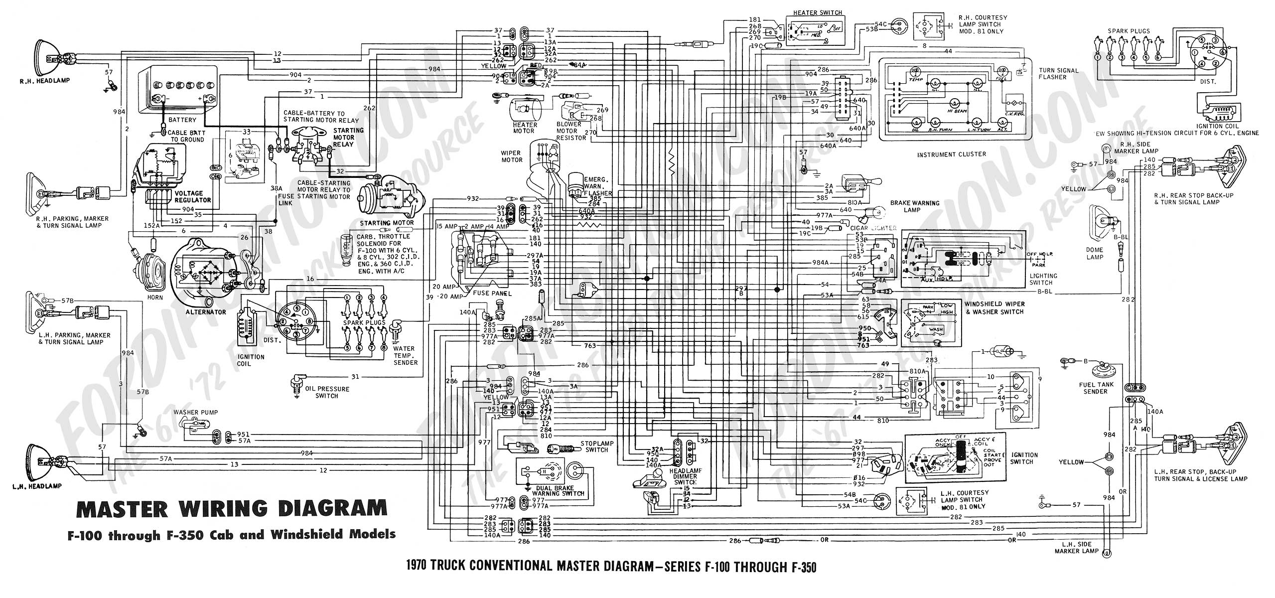
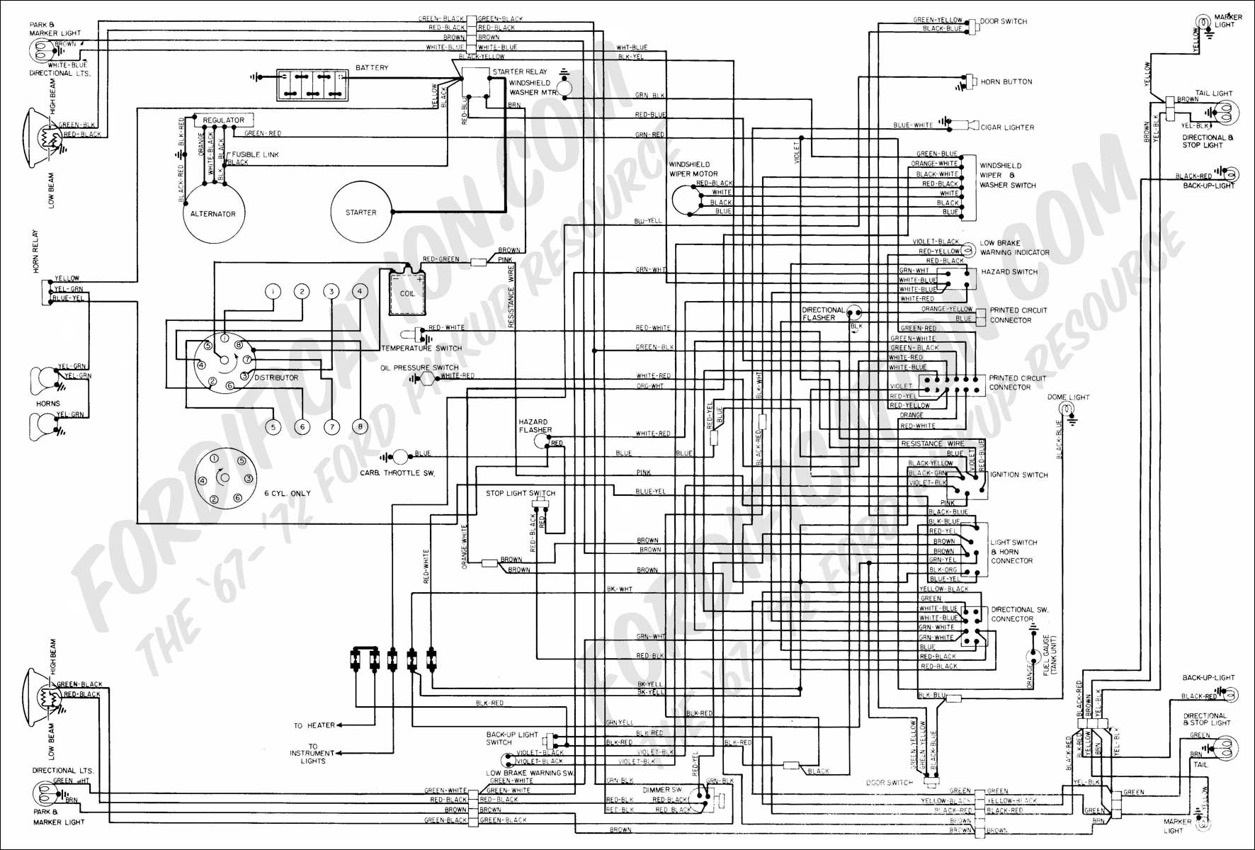
The headlamp switches on all 1970 Ford trucks (except "W"
models) employ two integral circuit breakers, one 12-amp for the
headlight circuit and one 15-amp for auxiliary circuits.
Connections to any point in the circuits controlled by the
headlamp switch will be on the auxiliary circuit breaker, except
connections to the #12 circuit (headlamp hi-beam, green
wire/black stripe), the #13 circuit (headlamp low-beam, red
wire/black stripe) and the #15 circuit (feed wire to the the
dimmer switch, red wire/yellow stripe. Connections to the 12-13
or 15 circuits (headlamp bulb circuits) should be avoided.
If
the total load on either headlamp circuit breaker exceeds the
breaker rating, the headlamps or taillamps will cycle on and off
indicating the overload. If this occurs, a portion of the added
lights must be wired through a relay, feeding the relay coil
from the headlamp switch.
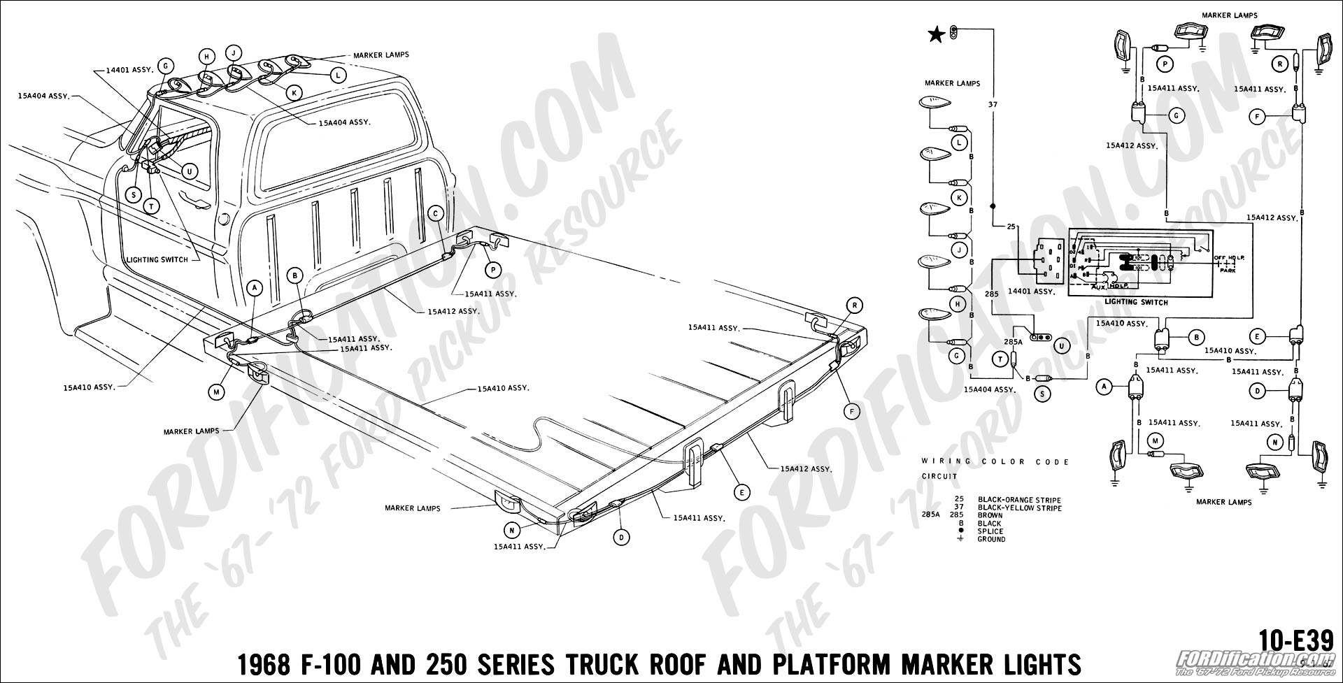
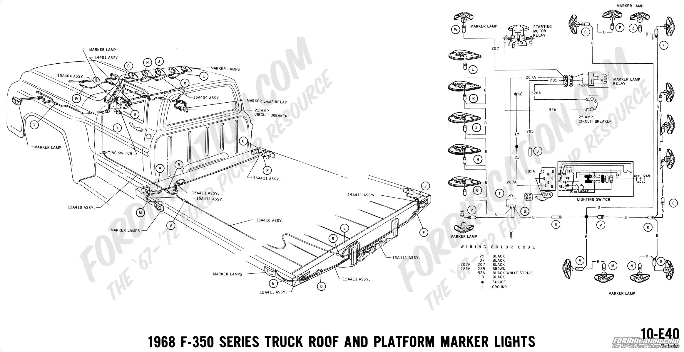
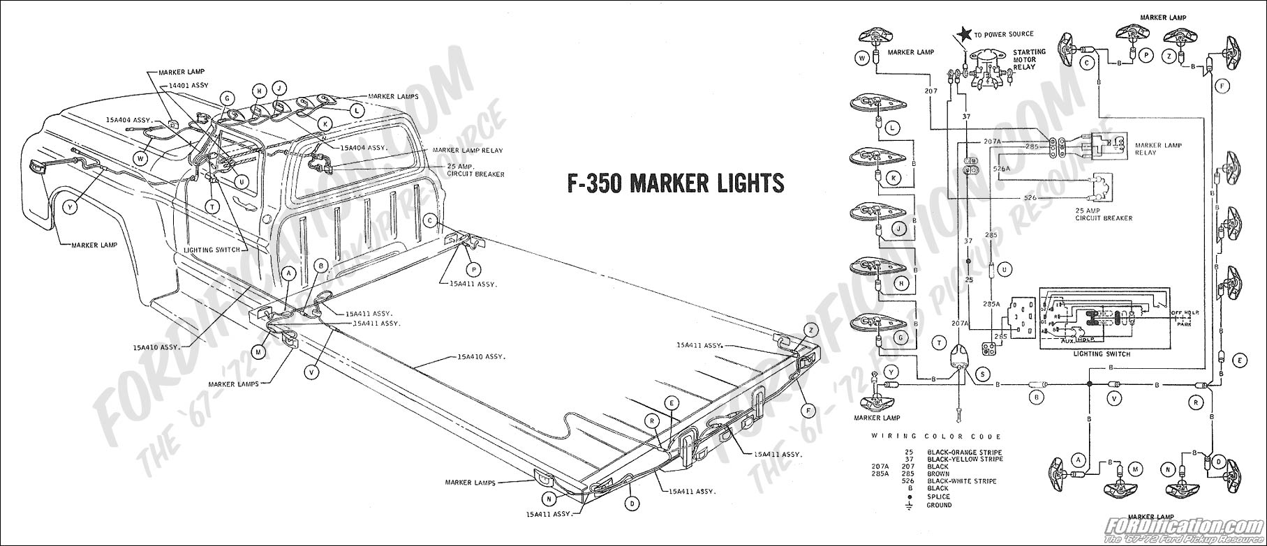
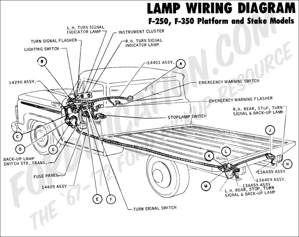
The
feed from added lights to be controlled by the headlamp switch
should be terminated in a male bullet connector and be connected
to the female bullet take-out (brown wire -- 285 circuit) on the
left-hand side of the instrument panel harness (near the
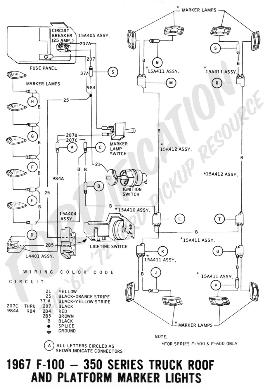
emergency brake). If the vehicle has roof marker lights, this
bullet will be occupied by the feed from the roof wires. In this
case fabricate a "Y" jumper to permit both connections to the
single connector.
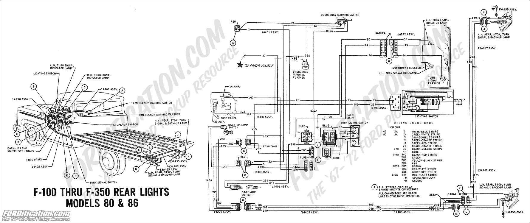
Rear
lights to be controlled by the headlight switch can be spliced
into the #285 circuit (brown wire) at any point in the taillamp
harness.
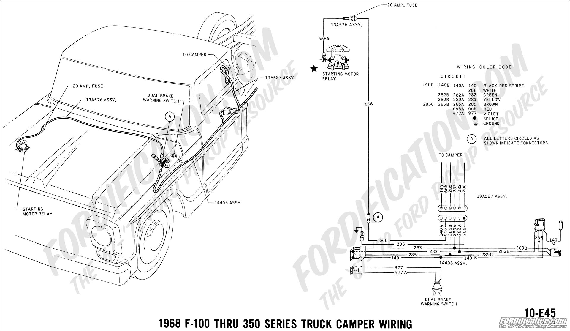
NOTE: The special Camper option on light trucks provides a plug
connector on the left-hand frame rail to which taillamp
connections can be made directly.
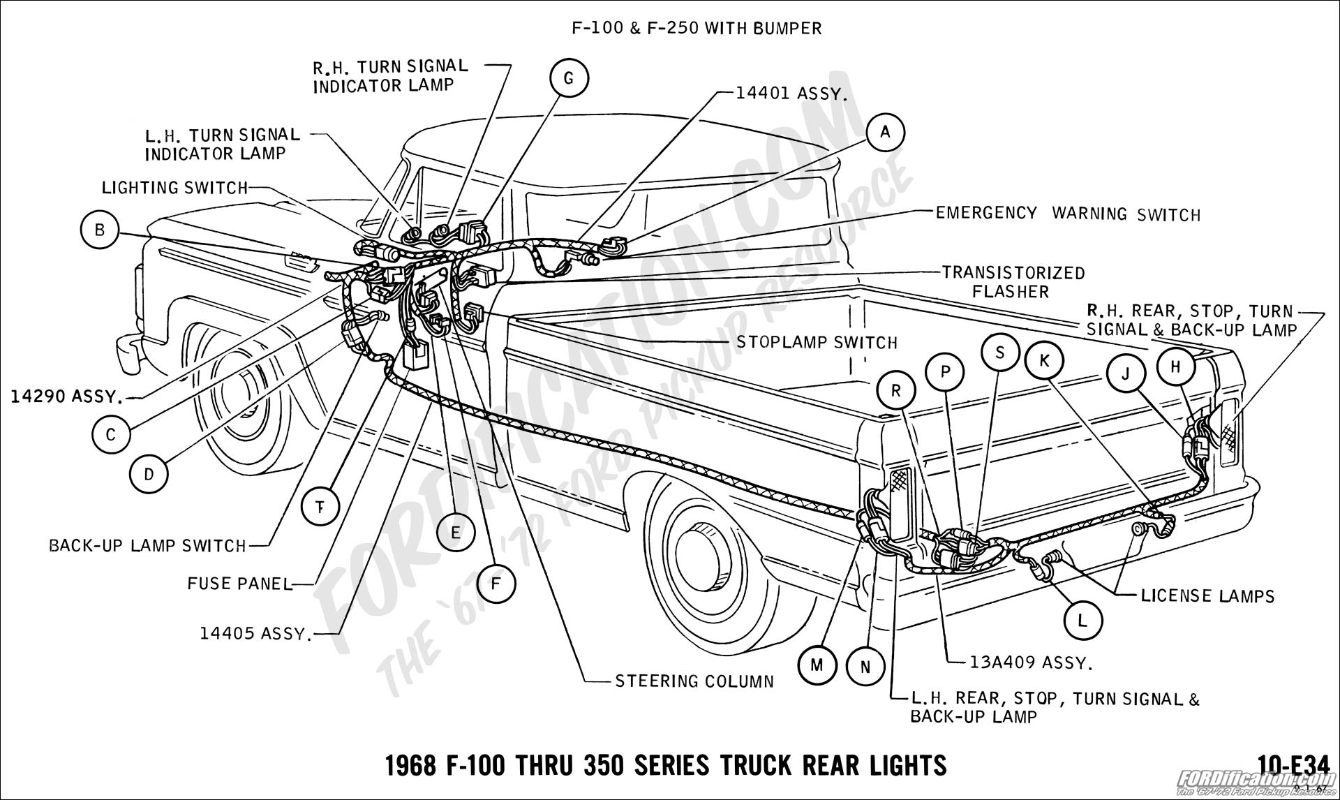
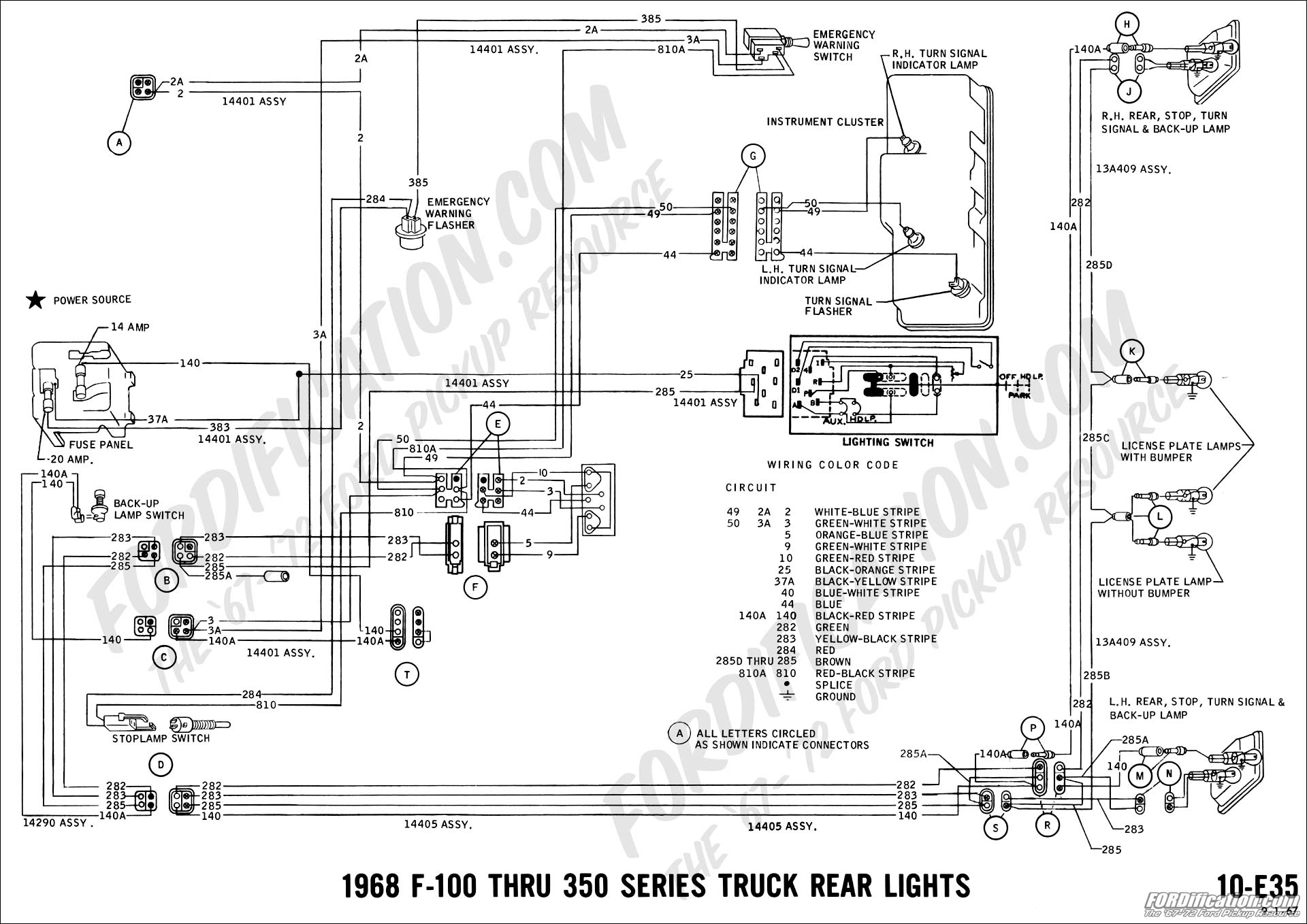
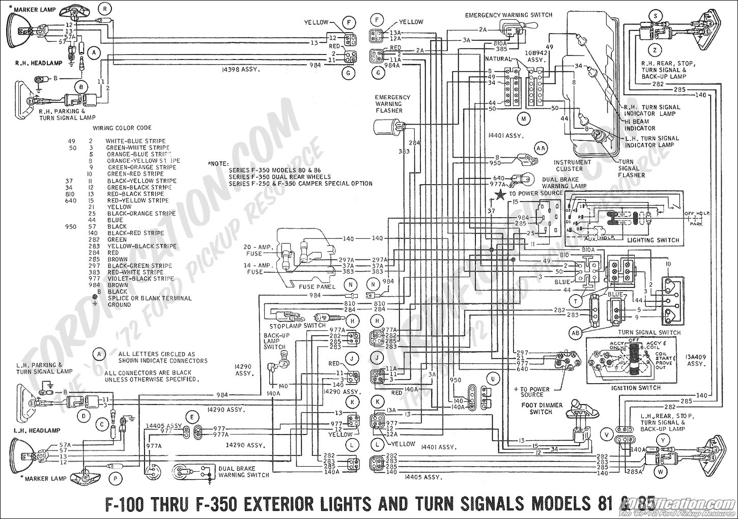
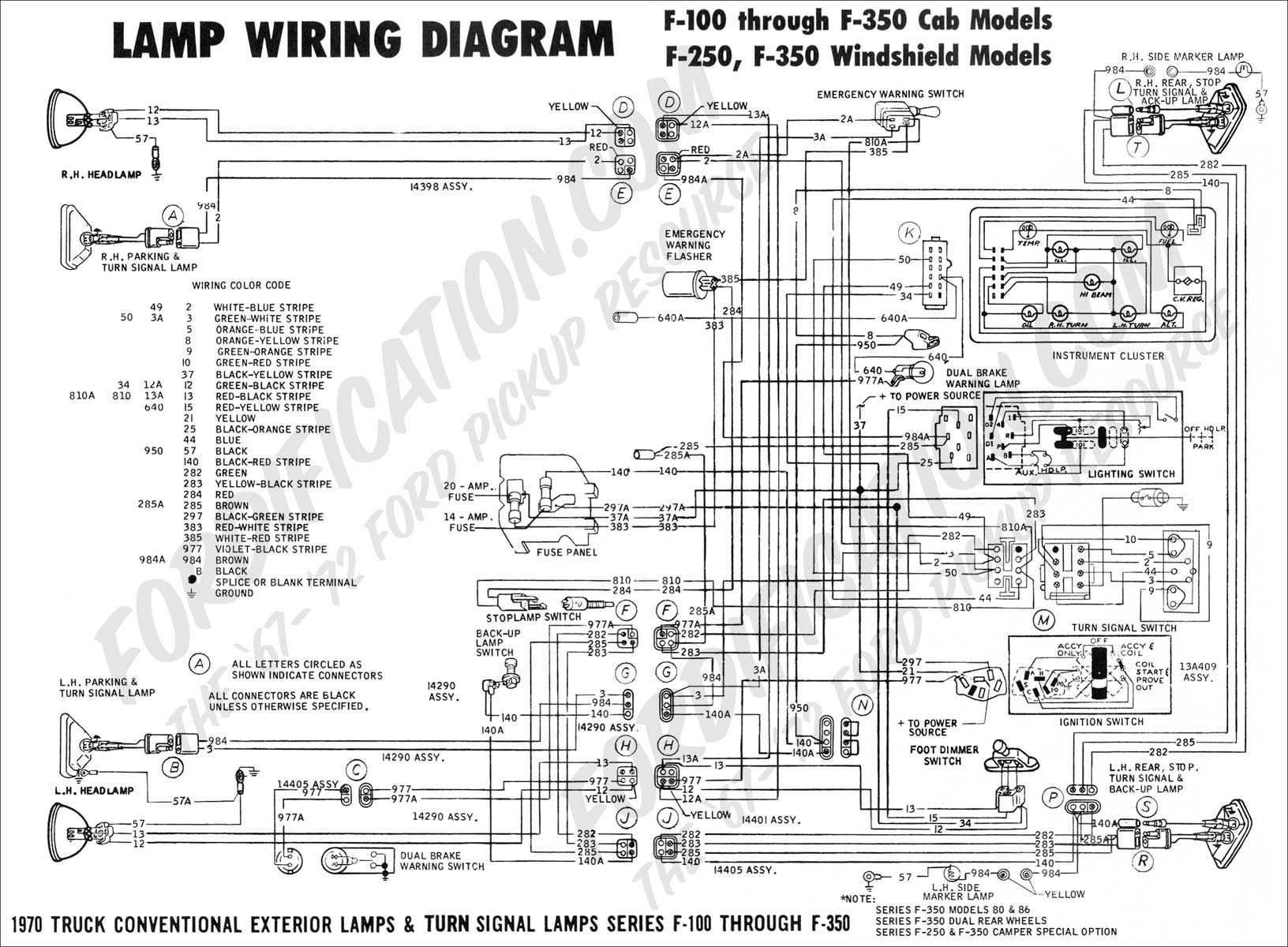
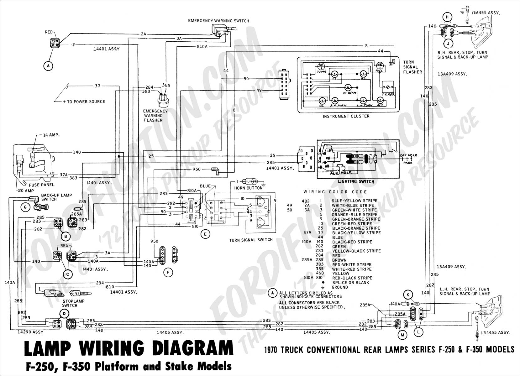
Lights controlled by Stop Lamp Switch and Turn Signal Indicator
F100
thru F350 trucks are equipped with a mechanical plunger stop
lamp switch which is mounted on the brake pedal arm. This switch
is designed for maximum loads usually less than the fuses or
circuit breaker in the circuit, but ample for normal stop lamp
loads. The maximum load is 12.5 amps and under no circumstances
are loads in excess of this value permissible.
If
only stop lamp function is desired for the added lights, splice
into the 810 circuit (red wire/black stripe) between the stop
lamp switch and the turn indicator switch.
If
only turn signal function is desired for the added lights,
connect right-hand lights to circuit #2 (white wire/blue stripe)
and left-hand lights to circuit #3 (green wire/white stripe).
This connection can be made by splicing into the wires near the
parking lights or near the steering column. (See note below.)
If
both turn signal and stop lamp function are desired for the
added lights, splice into the taillamp loom, using circuit 282
(green wire) for right-hand lights and circuit 283 (yellow
wire/black stripe) for left-hand lights. (See note below.)
NOTE
1) The turn signal switch used on light trucks has a maximum
rated current of 6.5 amps for right and left turning functions
and 8.0 amps for stop lamp function. Do not exceed these values
on the turn signals.
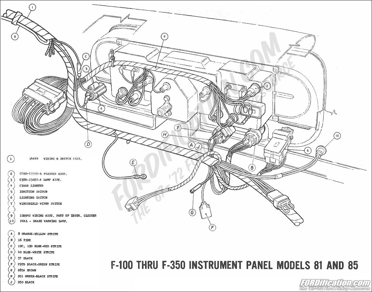
2) The turn signal and emergency flasher system on light trucks
utilizes two flashers, one for turn signal and one for emergency
flasher function. These flashers are designed to accommodate a
two-light (4.2 amps) load for the turn signal flasher and a
six-light load (12.6 amps) for the emergency flasher. If one
additional 2.1 amp light is added to each side (total 6 lamps)
the C8AB-13350-A turn signal flasher must be replaced with a
C6AB-13350-B flasher. The addition of two 2.1 amp lamps to each
side (total 8 lamps) will require replacing the existing two
flasher with a single C8TB-13350-A transistorized flasher and,
because of the complexity, is not recommended. The addition of
lights without a flasher revision will result in a very fast,
unacceptable flashing rate.
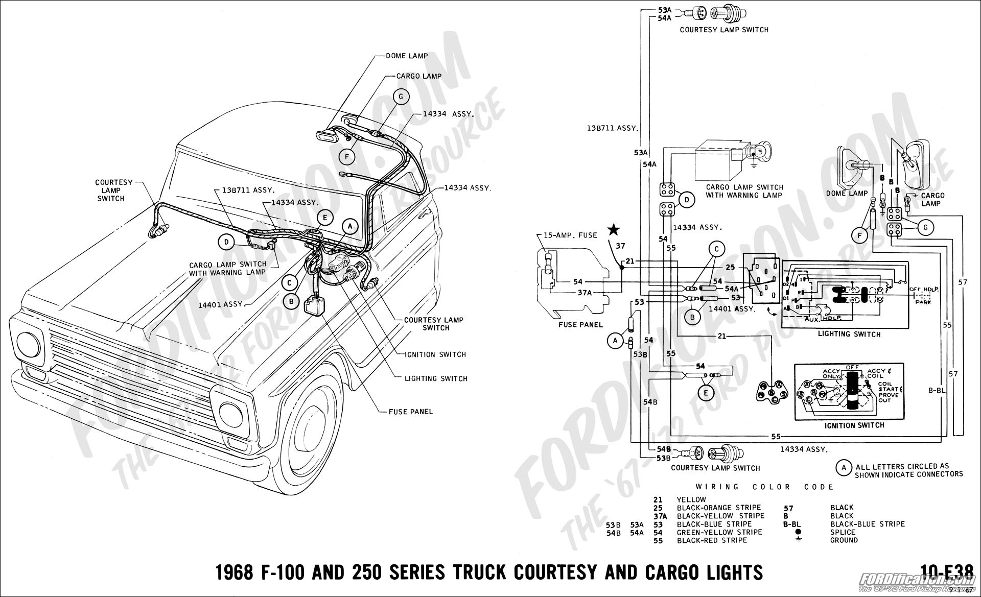
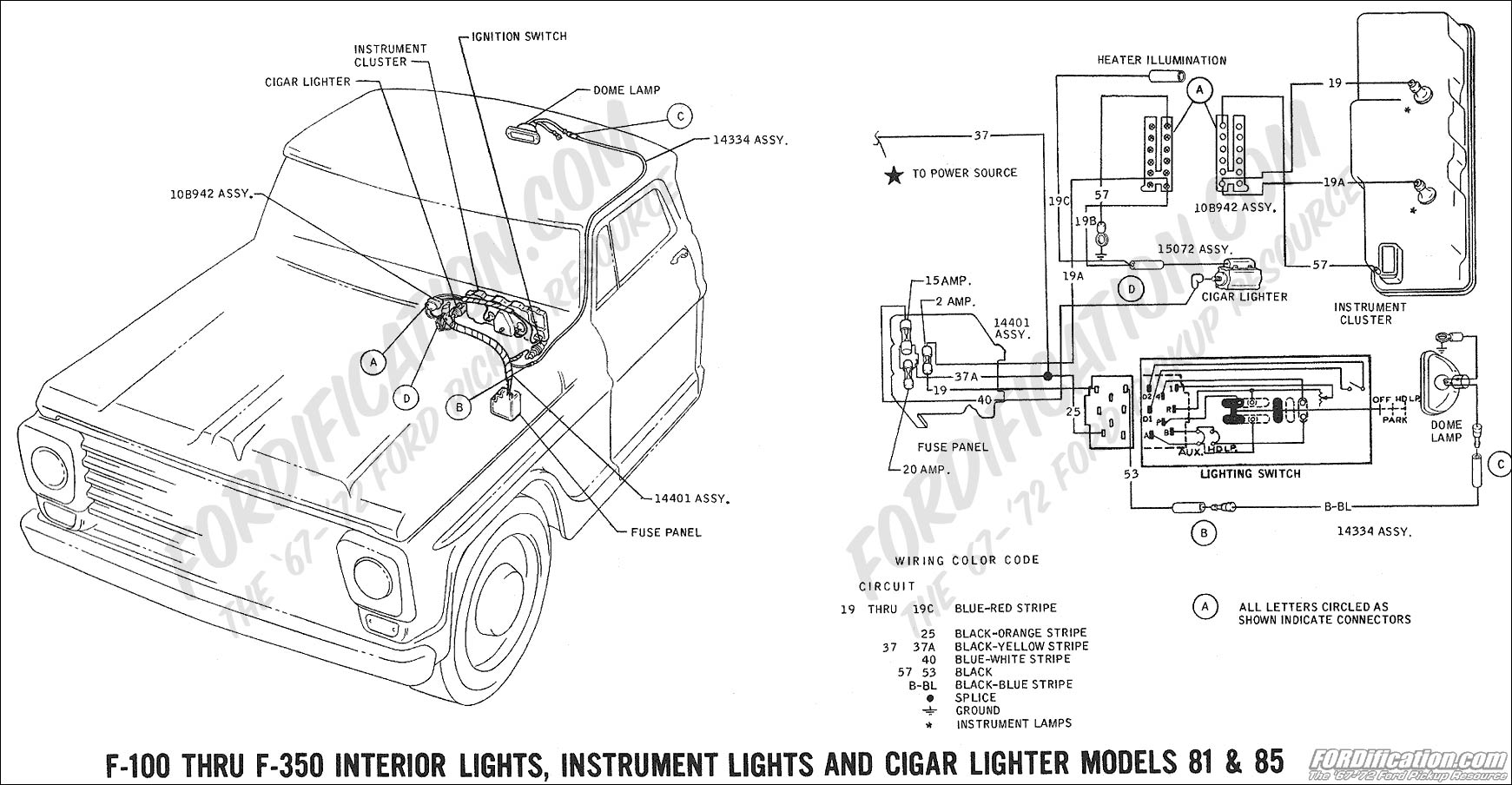
Added Lights or Accessories Controlled by Added Switches
For added electrical accessories that operate only when the
ignition is on -- terminate the feed wire from the hang-on
switch in a bullet connector and plug into the three-way
accessory plug on the instrument panel harness (single black
wire/green stripe). This circuit is limited by a 14-amp fuse.
Fuse "blow" requires the addition of a relay, with the coil fed
by a connection to the accessory terminal.
If the added accessory is desired to be operated with the key
off, the switch feed can be connected to the cigar lighter
(using a "Y" jumper) if the 15-amp fuse for that circuit is
sufficient. If heavier loads than the cigar lighter circuit will
carry are required, the switch feed should connect to the
starter relay "battery" terminal. |


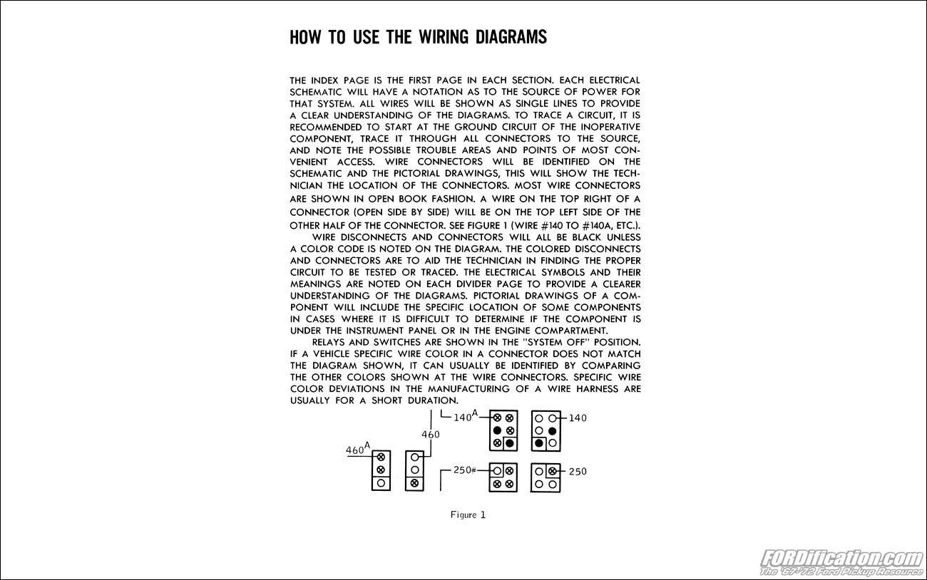
 PLEASE
READ: Most of the wiring diagrams posted on this page are
scans of original Ford diagrams, not aftermarket reproductions.
These were scanned and posted as very large files, to preserve
their readability. The 1969 diagrams and all others marked with a red asterisk (*)
were sent to via e-mail from various sources, so their quality
and/or size might not be as good or as detailed, however I still
gratefully acknowledge those who took the time to forward them
for posting. Eventually all diagrams posted here will be
hi-resolution for easier reading.
PLEASE
READ: Most of the wiring diagrams posted on this page are
scans of original Ford diagrams, not aftermarket reproductions.
These were scanned and posted as very large files, to preserve
their readability. The 1969 diagrams and all others marked with a red asterisk (*)
were sent to via e-mail from various sources, so their quality
and/or size might not be as good or as detailed, however I still
gratefully acknowledge those who took the time to forward them
for posting. Eventually all diagrams posted here will be
hi-resolution for easier reading.

